change the default load balancing algorithm in Weblogic Server

The Weblogic Server provides additional capability for managing the Clustered Environments using the load balancers with available load balancing algorithms.

The Weblogic Server Load Balancing Algorithms

  • Round Robin Load Balancing: Round Robin Load Balancing is the default load balancing strategy for clustered objects supported for RMI objects and EJBs
  • Weight -Based Load Balancing:  The Weight -Based Load Balancing in Weblogic Server assign each server with pre-defined weight.  Select Server -> Configuration -> Cluster tab in the Administration Console  and assign each server in the cluster with a numerical weight between 1 and 100.
  • Random Load Balancing:  The Random Load Balancing algorithm in Weblogic Server routes the requests randomly to the server. This algorithm is suitable for homogeneous cluster deployments where each server runs with the similar configurations.  The random method of load balancing applies only to EJB and RMI object clustering.
  • Server Affinity Load Balancing: The Server Affinity Load Balancing algorithm in Weblogic Server turns off load balancing for external client connections and prefers to use the existing Weblogic Server instance. If an object is configured for server affinity, the client-side stub attempts to choose a server instance to which it is already connected, and continues to use the same server instance for method calls.  There are 3 types of Server Affinity Load Balancing algorithms. Server affinity is used in combination with one of the standard load balancing methods: round-robin, weight-based, or random:
    • round-robin-affinity—server affinity governs connections between external Java clients and server instances; round robin load balancing is used for connections between server instances.
    • weight-based-affinity—server affinity governs connections between external Java clients and server instances; weight-based load balancing is used for connections between server instances.
    • random-affinity—server affinity governs connections between external Java clients and server instances; random load balancing is used for connections between server instances.

Steps to update the load balancing algorithm

1. Log into the Web Logic Admin Console
2. click Lock & Edit to make changes
3. Select Environments > Clusters
4. Select the Cluster Name from the given table.
5. Select the Load balancing algorithm for the available options.
6. Select Advanced and Enter the value for Service Age Threshold
7. Click Save
8. Click Activate changes.
Difference between Clustered environment and Non-clustered environment

The Weblogic Sever 12c provides the Clustered Infrastructure which is most suitable for production environment with enhanced security features. The blog provides the detailing on how Web Logic Clustered environment is different from Non-clustered environment.

Before that , please find below the blog link on the Web Logic Server Clustering Overview understanding clustering in Weblogic 12c

Clustered Environment vs Non-Clustered Environment in Weblogic 12c

The Clustered Environment is similar to Non-Clustered Environment except from the point that Cluster Web Logic Clustered Environment will provide below given additional features which are quire useful in case of time critical applications which are not supported through non-clustered environment.

  • Weblogic Server 12c Fail over mechanism :

Failure is the process when the web logic server is executing an object which could be the web logic resource, application component / service which needs to be completed as per the received service request but fails due to some reason.
In the Non-clustered environment, this failed object cannot be recovered or cannot instantiate a new object copying the failed object details to resume its processing. The clustered environment provides that support.

The clustered environment maintains the copy of the failed object.
The Web Logic program which manages failover process should be having the Object information which are in process including the location, operational status and overall progress of the in process object.
Web Logic Server also maintains the information regarding the IP Sockets and Java Naming and Directory Interface (JNDI) to share and maintain information about each object running in the Web Logic clustered environment.

Web Logic Server maintains the State of an object (what has been done for the object) using the Session Replication and Replica Aware Stubs techniques.

  • Load Balancing in Weblogic Server:

To avoid huge load on a single server, the Web Logic Clustered environment uses the technique of Load Balancing to ensure fair load on each server instance to increase performance, scalability and reliability of executed services.
Load balancing is the mechanism through which distribution of jobs will be performed using the Load Balancing Algorithm. By default, Web Logic uses Round-Robin Algorithm.

  • Automatic Migration Process in Weblogic Server:

Also Web Logic Clustering provides the Automatic Migration Process which means migration of clustered server instances from one machine to another at the run time to avoid failure of the in progress services / applications.


Understanding Web Logic Server 12c Clustering

The blog provides the overview of Clustering Configuration in he Weblogic Server 12c . Web Logic Server 12c is an Application Server which executes Web Application(WAR) and Enterprise Application (EAR) developed in Java.
The Oracle Fusion Middleware allows the installation of Web Logic Admin Server as well as Managed Servers like SOA Server, OSB Server and ADF Server to provide the complete deployment environment for Oracle Fusion Middleware Applications.

How to improve Weblogic Server 12c performance and Scalability


It has become common to have multiple server to provide performance as well as increased scalability and reliability when large applications with critical components to be executed in the heterogeneous environment. Thus, IT companies are preferring the usage of Web Logic Clustering as the optimized solution for running such applications.

What is Clustering in Weblogic Server 12c ?

Web Logic Clustering is the mechanism in which multiple Web Logic Server Instances are running and thus provides client with the single web logic server instance. Web Logic Cluster could have server instances on the same machine or can connect to multiple machines for increasing clustering capacity. It is important to note that each server instance in the Web Logic Cluster must be running with the same version of Web Logic Server.

To run the Web Logic Server through Admin Server, we need to CREATE the Web Logic DOMAIN. A Web Logic Domain is a combination of Web Logic server resources (Data Sources, Adapters, JMS Queues and Connections, etc.), application components, application services and server instances. Which means that a DOMAIN is a combination of multiple server instances which can be clustered, non-clustered, or a combination of clustered and non-clustered instances.
Each domain consists of Admin Server and other managed servers like SOA Server, OSB Server, ADF Server. The Admin Server configures, manages and monitors all other server instances. Thus, it clarifies that all server instances must resides in the same DOMAIN.

Also read to know how Web Logic Clustered environment is different from Non-clustered environment from the below given link

Clustered Environment vs Non-clustered Environment

Which Objects are considered as part of Web Logic Clustered Environment?

In the Web Logic Clustered Environment , each task executed in terms of Object. An application object could be different type, having different behavior including object invocation process, features and functions within an application when gets consumed. Below given are the main types of objects in the Web Logic Clustered deployment.

• Servlets
• JSPs
• EJBs
• Remote Method Invocation (RMI) objects
• Java Messaging Service (JMS) destinations

Web logic Server provides the support for Servlets and JSPs in the Clustering Environment by replicating the HTTP Session State of the Client that accesses servlets through clustered environment.
The HTTPS Sessions State can be maintained in the memory, a file based system or in the database by the Web Logic Server as per the configuration.
For the Enterprise Java Beans and Remote Method Invocation (RMI) objects, the Web Logic Server uses the Replica-Aware Stubs which can locate the instances of the object within the clustered environment.
In the object fails for EJBs or RMIs then the the stub detects the failure and retries the call on another replica

Which Objects are NOT considered as part of Web Logic Clustered Environment?

File services with File Shares and the Time Related Services will not be considered as part of Load Balancing or Failover techniques but can still be utilized in the Web Logic Clustered Environment as independent services.

The below given blog provides the distribution of domain file in the Distributed Weblogic Infrastructure

Distributing Domain File using Pack and Unpack


WebLogic Performance Tuning & Thread Management

The deployed application on Web Logic Server requires the availability of resources to execute the received service request and provide the corresponding response back to the application users.

All services are executed through Threads in the Web Logic Server. Each request serviced by the available thread from the Thread Pool. Thus, it is important to ensure that the available threads are not consumed completely and resulting into the Thread Deadlock and impacting the Web Logic Server performance.

Management of Threads in Previous Release before Web Logic 9.0
Till the previous Web Logic 9.0 Release, separate execute queues were maintained for different type of work (service request) executed by the Web Logic Server and users were provided with the creation of user defined thread pool. Thus, Web Logic admin had to manage multiple execute queues and multiple thread pools and required more time for diagnosing the exact reason for the consumption of stuck threads.
Management of Threads through Single Thread Pool
Web Logic Server provides Single Thread Pool and Single Execute Queue from Release 9.0 onwards.
How it works then with Single Thread Pool and overcome performance issue? Web Logic Server executes the received request based on priority. All type of work (service request) executed through Single Thread Pool and automatically maintains the Thread Count (increase / decrease of threads) and thus self –tuned itself.

Web Logic Server introduced Work Manager, which acts as the mechanism to prioritize the work and allocate the threads from the Thread Pool based on the rules defined for execution. The Web Logic Admin can use the pre-defined rules provided by the server or can setup the rules considering the run time performance, throughput and monitoring activities.

Below given are the pre-defined Rules /Constraints provided by Web Logic Server:

1) Fair Share Request Class:
2) Response Time Request Class:
3) Min Threads Constraint:
4) Max Threads Constraint:
5) Capacity Constraint
6) Context Request Class

Work Manager Types:
The Work Managers are classified into below given 3 types
1. Default Work Manager: If the application does not specify the Work Manager, then Web Logic Server Default Work Manager will be used to handle the thread management and request processing. It also manages self-tuning to avoid performance issues.
2. Global Work Managers: The global work manager will be available to all the deployed applications in the Web Logic Server. The application uses the work manager as a template. Each application will get its own instance at run time and thus Work Manager can execute respective application requests separately based on application instance.
3. Application Scoped Work Managers: Work Manager can be created in such a way that they perform requests for a specific application or module deployed in the Web Logic Server.

The application scope work managers can be defined in the Web Logic Admin console or can be added through the below given description files in the application
weblogic-application.xml
weblogic-ejb-jar.xml
weblogic.xml
What is the ideal situation to use Work Managers?
The Work Manager can be used when the below reasons are valid for the deployed application(s)
1. The default fair share (50) is not sufficient. This happens when multiple applications are deployed and one of the application request have more priority.
2. When it is required to set the response time goal.
3. When minimum thread constraint value need to be provided to avoid server deadlock


Work Manager request classes in WebLogic Server

Web Logic Server introduced Work Manager, which acts as the mechanism to prioritize the work and allocate the threads from the Thread Pool based on the rules defined for execution. The Web Logic Admin can use the pre-defined rules provided by the server or can setup the rules considering the run time performance, throughput and monitoring activities.

Below given are the pre-defined Rules /Constraints provided by Web Logic Server:

1) Fair Share Request Class:
2) Response Time Request Class:
3) Min Threads Constraint:
4) Max Threads Constraint:
5) Capacity Constraint
6) Context Request Class

Fair Share Request Class:
This rule configures the average thread use time required to process the received requests
Uses the relative value and not the percentage value
Minimum value is set to 1 and maximum value could be 1000

Example: Let say 2 Request Classes such as RC1 and RC2 are defined as 120 and 40, then the relative value will be 3:1 Thus the RC1 chance to get executed by the next free thread will be (120/160) = 0.75 %.
Similarly, the RC2 chance to get executed by the next free thread will be (40/160) =0.25 %

Response Time Request Class:
This rule configures the response time goal in milliseconds. The tolerable waiting time is computed by WebLogic Server by calculating the average response time goal for the received requests and schedules the request to ensure the average wait for the request should be less than to the defined tolerable waiting time.
Default value for response time goal is -1 which indicates that response time goal is not defined to be calculated at run time.

Context Request Class:
This rule configures the Request classes to the received service request based on the request context information like current user or current user group.

Example:
<work-manager>
<name>ResponseTime_RCWM</name>
<response-time-request-class>
<name>TestApp_ResponseTime</name>
<goal-ms>1000</goal-ms>
</response-time-request-class>
</work-manager>

<work-manager>
<name>Context_RCWM</name>
<context-request-class>
<name>TestApp_Context</name>
<context-case>
<user-name>system</user-name>
<request-class-name>high_fairshare</request-class-name>
</context-case>
<context-case>
<group-name>everyone</group-name>
<request-class-name>low_fairshare</request-class-name>
</context-case>
</context-request-class>
</work-manager>
It is preferable to set session timeout values to avoid session expiration while request wait in the Work Manager queue.

Work Manager defines constraints which sets the limit for the minimum and maximum threads that can be allocated to execute the received service requests. It also calculates the total number of received requests that can be queued (waiting to be executed in the queue) and rejects the received request if exceeds that limit to avoid server health issue.

Min Threads Constraint:
This rule sets the minimum limit of threads required for executing the received requests for processing.
Default value is unlimited.
Max Threads Constraint:
This rule sets the maximum limit of threads required for executing the received requests for processing

Capacity Constraint:
This rule sets the capacity value which when reached allows Web Logic Server to reject the received requests from processing.


How to Configure or update Advanced BPEL Properties in MBean Browser

Hello All,

The Prevous blog http://oracleappshelp.com/2019/05/22/how-to-configure-bpel-process-service-engine-properties-in-soa-12c/ provided the details on the properties related to the BPEL Service Engine .

There are advanced level properties also which are covered in this blog.

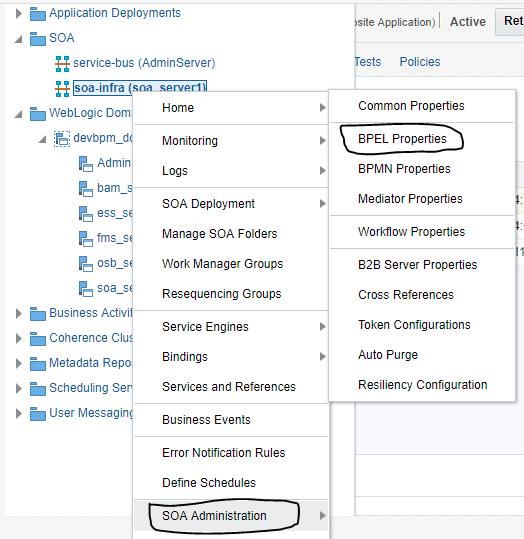
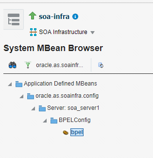
Log into the em console of the SOA Server and click on SOA Folder in the Administrator Area
Right click on SOA-INFRA and select SOA Administration -> BPEL Properties
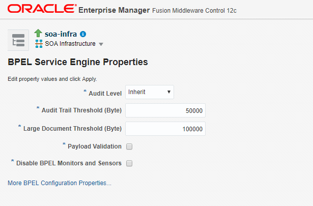
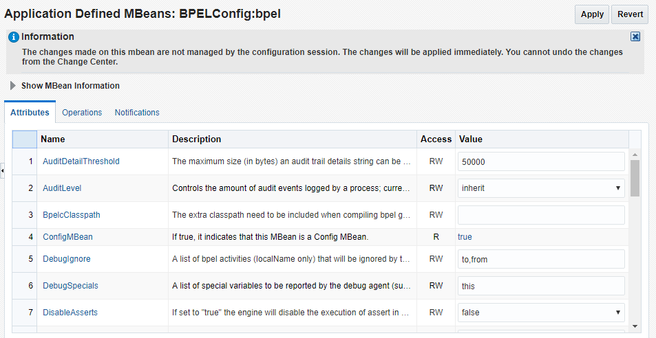
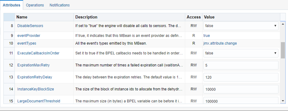
Click More BPEL Configuration Properties

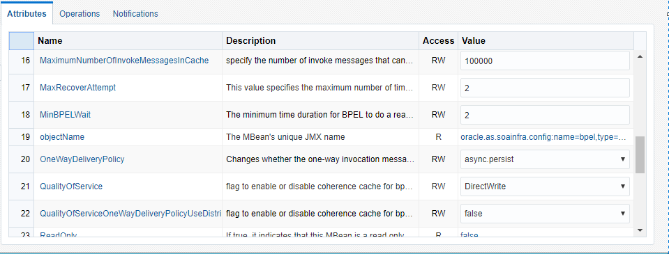
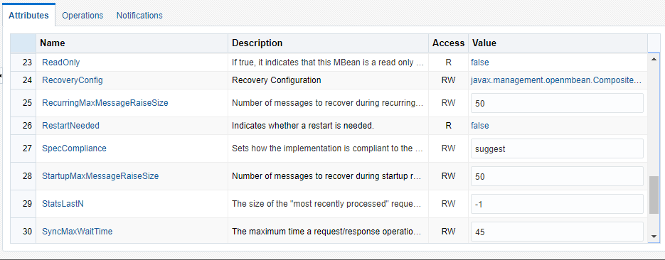
Below are the list of properties which can be defined in SOA Server as per the project need.

Advanced BPEL Properties in MBean Browser

Advanced BPEL Properties in MBean Browser

Advanced BPEL Properties in MBean Browser

Advanced BPEL Properties in MBean Browser

Advanced BPEL Properties in MBean Browser

Advanced BPEL Properties in MBean Browser


Configure BPEL Process Service Engine Properties in soa 12c

The blog depicts the steps to navigate and configure or change the default BPEL Service Engine Properties.

Log into the em console of the SOA Server and click on SOA Folder in the Administrator Area
Right click on SOA-INFRA and select SOA Administration -> BPEL Properties

Navigation- BPEL Service Engine Properties

Below are the properties which can be changed as per the project need

S. No Property Name Property Description
1 Audit Level The Audit Level can be defined as given below
• Inherit – This is the default logging same as SOA Infrastructure Audit Level Logging
• Off – No business flow instance tracking and payload tracking data is maintained
• Minimal- Only business flow instance tracking data is maintained. No Payload data details.
• Production – Business flow instance tracking data is maintained.
All other activity payload details are maintained but Payload details for assign activities are not maintained.
• Development – All events are logged. business flow instance tracking and payload tracking data is maintained
2 Audit Level Threshold The larger payloads will have large audit trail and thus stored in dehydration store table in chunks.
Specify the Numeric Value (size in bytes) of an instance Audit Trail before it is chunked.
3 Large Document Threshold To handle the large document, specify the maximum threshold value for the BPEL Variable before its contents are considered to be stored separately than rest of the instance scope data
4 Payload Validation Enable this option to validate Inbound and Outbound messages. Fault is raised for the Non-Schema complaint payload data
5 Disable BPEL Monitors and Sensors Enablement of this checkbox will disable BPEL monitors and sensors in the deployed SOA Composite applications.

BPEL Service Engine Properties


SDO Binding component services outbound integrations

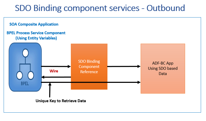
As we have discussed the SDO Inbound Integration with the ADF –BC Application, there could the SDO Outbound Integration where BPEL Process Service which invokes the Outbound Call to connect the ADF-BC Application to retrieve the data.

We discussed in previous blog (BPEL Data Operations using Entity Variables in SOA 12c) that in such cases the Oracle BPEL Process Manager uses the unique key which will get stored in the dehydration store. While invoking the Outbound call, BPEL Process Service binds the Unique Key and passes it as an Input to retrieve the required data.
Below given are the main steps that need to be followed
1) Oracle ADF-BC is the external application which is deployed as the SDO Service in the Service Infrastructure
2) In the BPEL Process Service, we need to create the partner link with the exposed SDO external service
3) To do so, we need to create the entity variable
4) Create the Binding key to map it as an input for the external ADF-BC Service

SDO Outbound Integrations


SDO Binding component services Inbound integrations

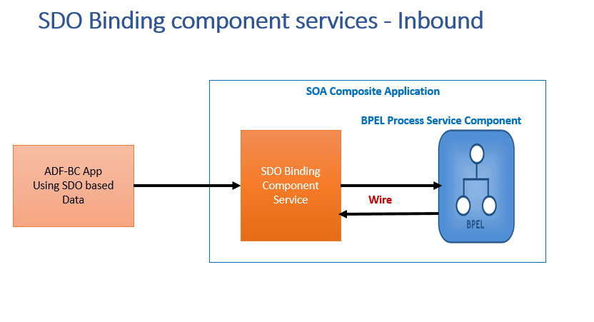
This blog discuss about the usage of SDO (Service Data Objects) Inbound Integrations with the ADF-BC Application. Refer the blog BPEL Data Operations using Entity Variables in SOA 12c  to understand how to perform the BPEL data operations using the data provider services through the usage of entity variables.

Till Release 10.X, only DOM format variables were supported. From Release 11g onwards, SDO format variables were introduced and supported in the BPEL Process Services and components can be converted into required formats as per the Business Process need (Example – Usage of ASSIGN Activity to convert the DOM based BPEL Process Service Component to SDO based format and vice –versa
Unlike DOM and SDO based variables, Entity variables supports SDO based data and enables a unique key which binds the value to data. A common Example could be Create Supplier Operation or Create Purchase Order using BPEL Process Service. This unique key gets stored in the dehydration store. When the data is to be retrieved, Oracle BPEL Process Manager performs the below steps:
1) It uses the Bind Entity Activity to map the unique key
2) Executes the data provider service to retrieve the data places into memory

SDO Inbound Integrations

The above given diagram depicts the SDO Inbound Integration where the ADF-BC Application Invokes the BPEL Process Service. The BPEL Process Service Component is converted from SDO based variables to DOM based Variables and executes the services as per the received operation.


SOA 12c – Entity Variables- delegating operations to data provider services

SOA 12c provides the capability to perform the BPEL data operations using the data provider services through the usage of entity variables. The data provider services perform the data operations behind the scenes and thus eliminates the usage of Database Adapter in the BPEL Process Service, enhancing the SOA runtime performance.
The common example of using entity variables with the Oracle Application Development Framework (ADF) which provides Business Component provider service using SDO based data to connect to the Data Store.
SDO is the specification provided to streamline the execution of SOA data from heterogeneous systems in the form of XML document, relational databases and web service being the source of information.

Entity variables using data provider service overcomes the below given issues:
1) Earlier the unsupported XML data source (Native Data) was required to be converted into XML Format before it can be processed using the SOA components.
2) The large payloads during the data conversion also leads to performance issue
3) In the previous release of SOA, the DOM form data was retrieved using the Database Adapter and was getting stored in the dehydrated data store. The stored data was not in sync with the target data store and thus might provide the stale data details.

The current SOA 12c Release overcomes this issue by providing the entity variables which retrieves the data using the data provider services (ADF –BC). Instead of storing the data in the dehydrated store, key is persisted (done using the BindEntity Activity in the BPEL Process).
Every time, this key will be referred to retrieve the data from the target data store using the data provider services, eliminating redundant data / stale data issue.

S. No 10.1.x Release 11g and 12c Release (Entity Variables)
1 Usage of Database Adapters for retrieving / saving the data Retrieving / saving of data is performed using data provider services ( ADF-BC)
2 Storage of data in the dehydrated store using the Oracle BPEL Process Manager Key is persisted for the transaction
3 Data variables are in the DOM( Document Object Model) Form Data variables are in the SDO ( Service Data Objects) Form

SOA 12c Outbound Integrations with SDO Binding Components

SOA 12c Inbound Integrations with SDO Binding Components


Interaction Pattern – Synchronous Transactions in SOA 12c

The blog discuss about ” How to invoke  Synchronous Transactions using SOA Suite Integration Pattern in SOA 12c” , “How to invoke Asynchronous Process from the  Synchronous Transactions in SOA12c”

Synchronous Transaction Integration Pattern

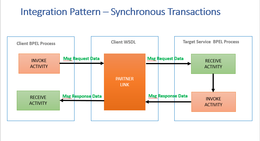
The synchronous integration pattern is the one where the application sends the message from the Client and receives the response back or we can say that its a 2 way communication process which is a combination of request and response.
The BPEL Process Service Component can be a Client who sends the request to the service and receives the response back or it could be the service who accepts the request and returns the response to the Client.

Synchronous Transaction Example in SOA 12c

Consider an example for synchronous transaction in SOA Composite application where user clicks on the application to get the list of employee in a particular department. In this scenario, the Department No. is the input from the Client and list of Employee will be the response sent back by the called service.

Integration-pattern-synchronous-transactions
Integration pattern: Synchronous Transactions

If the synchronous transaction uses BPEL Process as the Client, it needs to have the Invoke Activity. The port on the client side is used to send the request data to the Target Service and to receive the response (using the Reply Activity). The WSDL in the Client side BPEL Process Services defines the interaction depicting the portType, operation.

If the synchronous transaction uses BPEL Process as the Service, it needs to have the Receive Activity. The Service will execute the data as per the received request and returns either the Response or the Fault Message in case of any error occurred while processing the data. The WSDL in the Service side BPEL Process Services defines the interaction depicting the details including the fault defined.

Synchronous Transaction Invoking the Asynchronous Process:

If the synchronous transaction using the BPEL Process invokes an Asynchronous Process, then it will not have processed successfully as the callback response message is not acknowledge by the synchronous BPEL Process ad it will be timed out.

Sample for the portType and operation of the BPEL Process WSDL. The WSDL Operation supports both the Input and output messages for synchronous transaction processing.

<wsdl:portType name="SyncBPELProcess1">
<wsdl:operation name="process">
<wsdl:input message="client: SyncBPELProcess1RequestMessage" />
<wsdl:output message="client: SyncBPELProcess1ResponseMessage"/>
</wsdl:operation>
</wsdl:portType>

Interaction Pattern – One way messages in SOA 12c

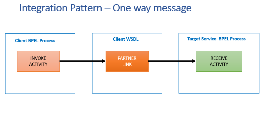
The blog explains the One way message integration pattern between the BPEL Process Service Component and external service(s).  The one way message integration pattern approach is also called as ” Fire and Forget message” 

There are scenarios where information need to be sent but it is not of utmost important to send immediately as these are independent actions need to perform once main service has been executed.

One Way message integration pattern example in SOA 12c


Consider an example of the user registration process requires user data validation, business process validation and then submission of user data in the custom user database table. Once the user registration process is completed, user receives the email notification for the confirmation of the user creation process. As user data is already being saved, the email notification service can be invoked once user registration process is completed.
The email notification process is the example of One-way message (or fire and forget) where client application sends the email notification and does not wait for the response.

To implement the one-way message service invocation process, the BPEL Process Service component needs the following
1. The message that client has to send to the target service. To accept the message from the client, the BPEL Process Service component needs a Receive Activity.
2. A Partner link for the target service to which message is to be sent.
3. An Invoke activity to invoke the partner link

Integration-pattern-one-way-messages
Interaction pattern one – way messages

Sample for the portType and operation of the BPEL Process WSDL. The WSDL operation includes only input message and No response message is supported.

<wsdl:portType name="OneWayMessageBPELProcess">
<wsdl:operation name="process">
<wsdl:input message="client:OneWayMessageBPELProcessRequestMessage" />
</wsdl:operation>
</wsdl:portType>